Alpine on an APU1C4 as a Stratum 1 NTP Server with PPS
This document assumes Alpine Linux is running on your APU, and has network access - installing Alpine Linux is covered elsewhere if you need that. If you’re using a different flavour of Linux, some commands will differ, but the process is mostly the same.
Getting the GPS portion working.
There’s not much to this - the device I’m using is a Ublox PCI-5S, which is actually mis-named… it’s a mini-PCIe form-factor but it’s not pinned for mini-PCIe at all, it’s pinned for USB. But if you plug it into one of hte mPCIe ports (take note! On the APU1 the socket closest to the GPIO/LPC pins is not mPCIe, it’s mSATA), it’ll likely be detected as a serial over USB port, and it’ll show up as /dev/ttyACM0:
[   12.028671] cdc_acm 4-2:1.0: ttyACM0: USB ACM device
[   12.036981] usbcore: registered new interface driver cdc_acm
[   12.036989] cdc_acm: USB Abstract Control Model driver for USB modems and ISDN adapters
So just apk add gpsd, set the device and baud rate appropriately in /etc/conf.d/gpsd (I’d previously, and unfortunately did not document this step, installed a higher-precision firmware, and then set the baud rate to default to 115200):
DEVICES="/dev/ttyACM0"
BAUDRATE="115200"

GPSD_OPTIONS="-n "
I also set -n on the options, because I didn’t want gpsd to wait for a client to connect before it starts checking in on how the receiver is doing getting a fix. In the end, this didn’t matter much.
Starting gpsd then using cgps eventually gets us a fix:
Status: 3D FIX (5436 secs)
My accuracy isn’t great, +/- about 30 meters, but I think that’s fairly good considering I rent, so the GPS antenna is sitting on a window sill in a south-facing window (in the southern hemisphere, I’m suspecting that’s about as sub-optimal as you can get). When we buy a house I’ll get a better antenna and do a more permanent installation.
The precision is dogshit!
Unfortunately, because it’s serial over USB, and USB is jittery, the signal isn’t great. In fact in my case, because my internet connection is relatively jitter-free, I actually get better precision from internet sources than I do from the Ublox GPS… not sure if I’m doing something wrong there. But the GPS will get me to within a second if my ISP decides to block NTP or something, and we can use PPS to get better precision. I’ll spare the technical explanations of PPS, because if you’re reading this and you’re not me, you probably already know what it is, you just noticed that this particular scenario is horrendously documented. Suffice to say PPS is a signal that the GPS will deliver a pulse, at the top of the second, with a high precision, and we can use that to get our NTP server very close.
Connecting the PPS signal
Avi provided this diagram, taken from this blog entry of someone else’s, after which he updated the last of the missing pads. I’m mirroring it here so it doesn’t disappear:
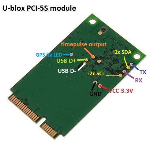
You’ll need to solder a wire to the pad labeled in orange, and this wire will go over to the GPIO pins on the APU. Which pin? That’s a whole other thing. PCEngines are kind enough to provide schematics for the APU1, and maybe I was just tired but they seemed really non-obvious to me. The GPIO block is labeled on page 14, but I spent too long trying to work out what that was and not enough time looking just to the left of it where the function of each GPIO pin is described as part of the LPC UART diagram. So to save time, I’ll transcribe the pinout here:
            GND  1     2  3.3VDC
CTS COM3 (GP00)  3     4  (GP01) DSR COM3
RTS COM3 (GP02)  5     6  (GP03) DTR COM3
 RX COM3 (GP04)  7     8  (GP05) TX COM3
DCD COM3 (GP06)  9    10  (GP07) RI COM3
CTS COM4 (GP10) 11    12  (GP11) DSR COM4
RTS COM4 (GP12) 13    14  (GP13) DTR COM4
 RX COM4 (GP14) 15    16  (GP15) TX COM4
DCD COM4 (GP16) 17    18  (GP17) RI COM4
            GND 19    20  5VDC
TL;DR: If you want your PPS device on COM3 (ttyS2), you want it on pin 9 (DCD). If you want it on COM4 (ttyS3), you’ll want it on pin 17 instead. According to a thread on the PCengines forum, the GPIO pins are 5v safe, and the PPS signal is 5V (or maybe 3.3v?), so you’re all set.
Enabling the 3rd and 4th Serial ports
Unless someone else has already done it, you’ll have to enable the serial ports on the device. Don’t be fooled, they’ll show up in Linux, but connecting a serial cable to them will receive no data if they’re not enabled in the BIOS! Reboot the machine with the serial cable connected to the serial console, and check the setup. A good indicator is if you have to press F12 for setup instead of F10, you’re probably going to need to flash because your BIOS will be too old to have the option to enable them.
If you need to flash, don’t fuck around trying to get Alpine to do it. It didn’t work for me, and I spent about 30 minutes trying. Just grab the TinyCore installer from PCengines, install that on a USB stick, drop the firmware rom file on there, eject it safely, and boot the APU from it.
Then flash it something like so (it goes without saying if you’re going to force on a boardmismatch, make sure the boards actually match!):
flashrom -w apu1_v4.12.0.1.rom -p internal:boardmismatch=force
It’ll take a few minutes, end with Verifying flash... VERIFIED., and then you can power-cycle the machine and get the “F10 for menu” notice. Do so, and enter the setup menu and enable the serial port(s) that you want to use for GPS:
  r Restore boot order defaults
  n Network/PXE boot - Currently Disabled
  u USB boot - Currently Enabled
  t Serial console - Currently Enabled
  k Redirect console output to COM2 - Currently Disabled
  o UART C - Currently Enabled
  p UART D - Currently Enabled
  w Enable BIOS write protect - Currently Disabled
  x Exit setup without save
  s Save configuration and exit
I had big plans of running two receivers, so I enabled both, but you only need to enable what you want to use, if you want to save GPIO pins for other projects. Save and exit, and you should be all set.
Enabling the PPS device
You’ll probably find that Linux has gone ahead and added a PPS device for you, but this one’s connected via USB, so it’s utterly unusable. We’ll have to add one, and it’s pretty easy:
apk add util-linux
modprobe pps_ldisc # probably not required, as you'll likely already have
                   # it, including it here for scripting purposes.
ldattach 18 /dev/ttyS2 # open the device /dev/ttyS2 for discipline 18 (PPS)
This should give you a new source:
[ 1512.752080] pps pps1: new PPS source serial2
[ 1512.752120] pps pps1: source "/dev/ttyS2" added
You can verify this if you don’t trust anything - cat /sys/class/pps/pps1/path should return the device you passed to it.
Pointing Chrony at the PPS source
I mostly copy+pasted shit from other sites, so this part is more or less left up to an exercise for the reader, but here’s the relevant lines from chrony.conf:
refclock SHM 0 delay 0.5 refid UBLX
refclock PPS /dev/pps1 refid PPS poll 5 filter 80 precision 1e-9
Because the polling interval is 2^5, it’ll take about 30 seconds give or take before the PPS signal will show up in sources, but after some time Chrony seemed to figure out it was the best source and switched to it:
MS Name/IP address         Stratum Poll Reach LastRx Last sample
===============================================================================
#- UBLX                          0   4   377    17    +43ms[  +43ms] +/-  251ms
#* PPS                           0   5   377    25    -52ns[  -76ns] +/-  189ns
^- time.srv.ualberta.ca          2   9   377   493   -100ms[ -100ms] +/-  138ms
^- time03.nevondo.com            2  10   377   483   -100ms[ -100ms] +/-  178ms
^- dev1.sjelab.net               2   9   377   313    -98ms[  -98ms] +/-  119ms
^- time.nullroutenetworks.c>     2  10   377   115    -85ms[  -85ms] +/-  122ms
Now I’m not a time nerd, so I don’t have the faintest idea of what any of the configuration options for Chrony do… I’ll have to research them and work it out, but this should get you going.